Saturday, September 1, 2012

Different Network connectivity Devices

The various type of networking devices are:
1. Repeater
2. Hub
3. Bridge
4. Switch
5. Router

1 Repeater/Hub
* It is not an intelligent devices
* It works with bites
* Uses broadcast for communication
* bandwidth is shared
* Half-duplex communication

2.Bridge
* It is an intelligent devices
* It is software based
* In bridge port quantity is very less
* it is a layer 2 deices
* data transmission type is frame

3. Switch
* It is an intelligent device
*It maintains MAC address table (hardware address)
* Each port of the switch has fixed bandwidth
*It works with Flooding and Unicast
* Supports full duplex communication
* Function of a Switch
    -> MAC Address Learning
    -> Forwarding

4. Router
* It is a Layer 3 device
* It is an Intelligent device
* It works with Logical Addressing (i.e. IP, IPX, Apple Talk)
* It works with Fixed bandwidth
* Function of Router
    ->Inter Network Communication
    -> Best path selection
    -> Packet Switching
    -> Packet Forwarding

Different Network Connectivity Media

The various type of network Connectivity Media are:

1. Guided Media

     I. Co-axial Cable

     II. Twisted pair
            a. UTP
            b.STP

    III. Fiber Cable

2. Unguided Media

    I Infrared

    II RF

Saturday, August 25, 2012

IP Addresses

To identify the system on a network is called IP address, it is a logical address, it is a network layer (layer3) address.
There are Two type of IP address
1. IP version 4 (32 bit)
2. IP version 6 (128 bit)
----------------------------------------------------------------------------------------------
IP version 4
IPv4 addresses are 32 bits long, broken up into 4 bytes, and separated by decimals, commonly called the dotted decimal format. Two components make up the address: a network and host number.
In IPv4 there are total five classes : Class A, Class B, Class C, Class D, Class E
Class A addresses have, by defaults, 8 network bits, Class B addresses have 16 bits, and Class C addresses have 24  network bits


IP Address Components
Two components make up a Class A, B and C  IP Address: network and host. The host portion is actually broken into three subcomponents: the network address, the host address, and the directed broadcast address.


an IP address that begins with 8 in the first octet is in a Class A network, so the network part of the address is the first byte, or first octet. An address that begins with 130 is in a Class B network. By definition, Class B addresses have a 2-byte network part, as shown. Finally, any address that begins with 199 is in a Class C network, which has a 3-byte network part. Also by definition, a Class A address has a 3-byte host part, Class B has a 2-byte host part, and Class C has a 1-byte host part.
All Possible Valid Network Numbers


Public and Private Addressing

The ICANN (formerly IANA) and its member organizations manage the process of assigning IP network numbers, or even smaller ranges of IP addresses, to companies that want to connect to the Internet. After a company is assigned a range of IP addresses, only that company can use that range. Additionally, the routers in the Internet can then learn routes to reach these networks, so that everyone in the entire Internet can forward packets to that IP network. Because these IP addresses can be reached by packets in the public Internet, these networks are often called public networks, and the addresses in these networks are called public addresses.
Private Address Space
* There are certain addresses in each class of IP address that are reserved for Private Network. These addresses are called private addresses
* These addresses are not Routable or valid on internet.


IPv4 Address Type
* Unicast
* Broadcast
* Multicast


-----------------------------------------------------------------------------------------------------
IP version 6
IPv4 address is 32 bits in length, there 232  actual IP address, which is 4.3 billion addresses. Not all of these are usable, however: only 3.7 billion of these are actually usable. Many addresses are reserved, such as
* Research (239-254)
* Broadcast (255)
* Multicast (224-239)
* Private (10,172.16, and 192.168)
* Loopback addresses (127)
Unlike 32 bit IPv4 addresses, IPv6 uses a 128 bit address. This allows for 3.4 x 1038  addresses, which is enough for many IP addresses for each person on Earth, and probably multiple planets.
    The 128-bit IPv6 address is written in hexadecimal notation, with colons between each quartet of symbols. Even in hexadecimal, the addresses can be long. However, IPv6 also allows for abbreviations,  The table also summarizes some of the pertinent information comparing IPv4 addresses with IPv6.
IPv4 Versus IPv6


IPv6 Features
* Very large address space
* Security
* Mobility
* Streamlined encapsulation
* Transition capabilities

Example of IPv6 addressing


IPv6 Address Type
* Unicast Address
* Global Unicast Address
* Link-local Address
* Unique Local Address
* Multicast Address
* Anycast Address

Special Addresses of IPv6
 1.  0:0:0:0:0:0:0:0  Equals  ::  =>This is the equivalent of IPv4`s 0.0.0.0, and is typically the source address of a host when you are using state full configuration.
2. 0:0:0:0:0:0:0:1  Equals  ::1 =>The equivalent of 127.0.0.1 in IPv4
3. 0:0:0:0:0:0:192.168.100.1 => This is how an IPv4 address would be written in a mixed IPv6/IPv4 network environment.
4.  2000::/3 =>The global unicast address range.
5. FC00::/7 => The unique local unicast range.
6. FE80::/10 => The link-local unicast range.
7. FF00:/8 => The multicast range
8. 3FFF:FFFF::/32 => Reserved for example and documentation
9. 2001:0DB8::/32 => Also reserved for examples and documentation
10. 2002::/16 => Used with 6to4, which is the transition system.


IP Subnetting

Subnet Mask
* Subnet Mask differentiate the Network and Host portions of an IP address.
* Represented with all 1`s in the network portion and with all0`s in the host portion.
Example of subnet mask
* Class A : N.H.H.H
11111111.00000000.00000000.00000000
Default subnet mask for class A is 255.0.0.0
* Class B : N.N.H.H
11111111.11111111.00000000.00000000
Default subnet mask for class B is 255.255.0.0
* Class C : N.N.N.H
11111111.11111111.11111111.00000000
Default subnet mask for class C is 255.255.255.0

How Subnet Mask Works?
IP Address    :    192.168.1.1
Subnet Mask:    255.255.255.0
ANDING PROCESS:
192.168.1.1    =11000000.10101000.00000001.00000001
255.255.255.0=11111111.11111111.11111111.00000000
---------------------------------------------------------------
192.168.1.0    =11000000.10101000.00000001.00000000
---------------------------------------------------------------
The output of an AND table is 1 if both its input are 1
for all other possible inputs the output is 0.

SUBNETTING
Dividing the large network into small sub network is called subnetting. the main purpose of using subneting is to utilize the IP address, and save the IP address. By converting host bit into network bit is called subneting.
* Creating Multiple independent Network from a Single Network.
* Converting Host Bits into Network Nits.
    i.e. Converting 0`s into 1`s
* It is also know as FLSM (fixed Length Subnet Mask)
* Efficiently utilize the IP address
* Subnetting Can be Performed in two way:
    => FLSM (fixed Length Subnet Mask)
    => VLSM (Variabe Length Subnet Mask)
* Subnetting can be done based on requirement
    => Number of Networks required?
    => Number of Hosts required?
Example of Subnetting :
QUE:1. Requirement of Network is 2?
ANS: 
Class C : N.N.N.H
Class C 192.168.1.0
No. of subnet
     = 2n-2 > Req. of subnet
     = 22-2 > 2 (-2 is for First & Subnet Range)
     = 4-2
     = 2 Subnet
No. of Host
     = 2h-2 (-2 is for Network ID & Broadcast ID)
     = 26-2
     = 64-2
     = 62 Host/Subnet
Customized subnet mask
255.255.255.192
Host Range
192.168.1.64 to 192.168.1.127
192.168.1.128 to 192.168.1.191

QUE:2. Requirement of Host is 40?
ANS: 
Class C : N.N.N.H
Class C 192.168.1.0
No. of Host
     = 2h-2 > Req. of Host
     = 26-2 > 40 (-2 is for Network ID & Broadcast ID)
     = 64-2
     = 62 Host/Subnet
No. of Subnet
     = 2n-2 (-2 is for First & Subnet Range)
     = 22-2
     = 4-2
     = 2 Subnet
Customized subnet mask
255.255.255.192
Host Range
192.168.1.64 to 192.168.1.127
192.168.1.128 to 192.168.1.191


Sunday, August 19, 2012

VLSM Super netting

VLSM (Variable Length Subnet Mask)
Dividing the subnet into small subnet for efficiently utilize of address is called a VLSM or super netting, in one major network we have more than one subnet mask, inter department routing is not possible. 
* Subnetting a subnet is called as Variable Length Subnet Mask.
* VLSMs provide the capability to include more then one subnet mask within a major network.

Scenario:
* freetest hub is having 100 PC
    freetest hub - 192.168.1.0/24
`   -MCSE
    -CISCO
    -FIREWALL
    -SOLARIS
    -TRAINING
    Administrator's requirement: Inter-department cpmmunication should not be possible?
    Best Solution is : FLSM (i.e. Subnetting)
* Now we are also having sub department
1 MCSE 
2 CISCO
   a. CCNA
    b. CCNP
 3 FIREWALL
   a.  ISA
    b. Checkpont
    c. NetASQ
    d. Clavister
    e. Cisco PIX 
 4 SOLARIS   
    a. Linux
    b. Unix
    c. Solaris
5 TRAINING
Administrator does not want inter-department communication in the sub department?
ANSWER:
You  will use the subnet range to futher divide it nto smaller ranges, this time its Subnetting of a  Subnet i.e. VLSM.
Class C : N.N.N.H
Class C 192.168.1.0
No. of subnet
     = 2n-2 > Req. of subnet
     = 23-2 > 2 (-2 is for First & Subnet Range)
     = 8-2
     =6 Subnet
No. of Host
     = 2h-2 (-2 is for Network ID & Broadcast ID)
     = 25-2
     = 32-2
     = 30 Host/Subnet
Customized subnet mask
255.255.255.224
Host Range
1 MCSE           =>192.168.1.32 - 1.63/27
2 CISCO           =>192.168.1.64 - 1.95/27
    ccna
    ccnp
3 FIREWALL =>192.168.1.96 - 1.127/27
         ISA    
         Checkpont
         NetASQ 
         Clavister 
          Cisco PIX 
4 SOLARIS    =>192.168.1.128 - 1.159/27
       Linux
       Unix
        Solaris
5 TRAINING =>192.168.1.160 - 1.191/27
Calculation of VLSM for CISCO Dept.
Class C : N.N.N.H
Class C 192.168.1.64
No. of subnet
     = 2n > Req. of subnet
     = 21 > 2
     = 2
     = 2 Subnet
No. of Host
     = 2h-2 (-2 is for Network ID & Broadcast ID)
     = 24-2
     = 16-2
     = 14 Host/Subnet
Customized subnet mask
255.255.255.240
Host Range
1 MCSE           =>192.168.1.32 - 1.63/27
2 CISCO           =>192.168.1.64 - 1.95/27
    ccna =>192.168.1.64 - 1.79/28
    ccnp =>192.168.1.80 - 1.95/28
3 FIREWALL =>192.168.1.96 - 1.127/27
4 SOLARIS    =>192.168.1.128 - 1.159/27
5 TRAINING =>192.168.1.160 - 1.191/27

Calculation of VLSM for Firewall Dept.
Class C : N.N.N.H
Class C 192.168.1.96
No. of subnet
     = 2n > Req. of subnet
     = 23 > 5
     = 8
     = 8 Subnet
No. of Host
     = 2h-2 (-2 is for Network ID & Broadcast ID)
     = 22-2
     = 4-2
     = 2 Host/Subnet
Customized subnet mask
255.255.255.252
Host Range
1 MCSE  =>192.168.1.32 - 1.63/27
2 CISCO  =>192.168.1.64 - 1.95/27
                ccna =>192.168.1.64 - 1.79/28
                ccnp =>192.168.1.80 - 1.95/28
3 FIREWALL =>192.168.1.96 - 1.127/27
                      ISA          =>192.168.1.96 - 1.99/30
                     Checkpont=>192.168.1.100 - 1.103/30
                     NetASQ    =>192.168.1.104 - 1.107/30
                     Clavister    =>192.168.1.108 - 1.111/30
                     Cisco PIX  =>192.168.1.112 - 1.115/30
4 SOLARIS    =>192.168.1.128 - 1.159/27
5 TRAINING =>192.168.1.160 - 1.191/27

Calculation of VLSM for Solaris Dept.
Class C : N.N.N.H
Class C 192.168.1.128
No. of subnet
     = 2n > Req. of subnet
     = 22 > 3
     = 4
     = 4 Subnet
No. of Host
     = 2h-2 (-2 is for Network ID & Broadcast ID)
     = 23-2
     = 8-2
     = 6 Host/Subnet
Customized subnet mask
255.255.255.248
Host Range
1 MCSE  =>192.168.1.32 - 1.63/27
2 CISCO  =>192.168.1.64 - 1.95/27
                ccna =>192.168.1.64 - 1.79/28
                ccnp =>192.168.1.80 - 1.95/28
3 FIREWALL =>192.168.1.96 - 1.127/27
                      ISA          =>192.168.1.96 - 1.99/30
                     Checkpont=>192.168.1.100 - 1.103/30
                     NetASQ    =>192.168.1.104 - 1.107/30
                     Clavister    =>192.168.1.108 - 1.111/30
                     Cisco PIX  =>192.168.1.112 - 1.115/30
4 SOLARIS    =>192.168.1.128 - 1.159/27
                    Linux =>192.168.1.128 - 1.135/29
                    Unix =>192.168.1.136 - 1.143/29
                    Solaris =>192.168.1.144 - 1.151/29
5 TRAINING =>192.168.1.160 - 1.191/27


Saturday, August 18, 2012

OSI Reference model

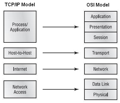
In 1984, the International Organization for Standardization (ISO) developed the OSI Reference Model . OSI model is used to describe how information is transferred from one networking component  to another network component.

    OSI (Open System Interconnect) model separates the network communication process into seven layers, each layer has a different but specific processing  function. application Layer (layer 7), Presentation Layer (layer 6), Session Layer (layer 5), Transport Layer (layer 4), Network Layer (layer 3), Data Link Layer (layer 2), Physical Layer (layer 1).


* Application, Presentation and Session layer  call as "Upper Layer OR software Layer"
* Transport layer  call as "heart of OSI model"
* Network, Data link and Physical layer  call as "Lower Layer OR  Hardware Layer"

Devices and Protocols


Layer7:  Application Layer
    The seventh layer , or topmost layer, of the OSI Reference Model is the application layer, it is a responsible for providing network services to the users, it is also called as Desktop layer, Identification of all services done by using Port Numbers.
* Total No Of Port (0  to 65535)
* Reserved Port  (0 to 1023)
* Open Client Port (1024 to 65535)

Layer6: Presentation Layer
    The six layer , of the OSI Reference Model is the presentation layer, it is a responsible for converting data into standard format. the presentation layer determines how data is transmitted and represented to the user.
Example: ASCII, JPEG, MPEG, MP3 etc.
 function of presentation layer:
    * Encoding and Decoding
    * Encryption and Decryption
    * Compression and Decompression

Layer5: Session Layer
    The fifth layer, of the OSI Reference Model is the session layer, the session layer is responsible for initiating the  setup and teardown of connections. the session layer is responsible for setting up, maintaining and tearing down network connections.
Example: RPCs ( Remote Procedure Calls), NFS ( Network File System) and SQL( Standard Query Language ).

Layer4: Transport Layer
    The fourth layer, of the OSI Reference Model is the transport layer,it is a heart of OSI layer, it is responsible  for end to end connectivity. Transport Layer provides a variety of services between two host computers, including connection establishment and termination, flow control, error recovery, and segmentation of large data blocks into smaller parts for transmission.
Following task are performed in this layer:
* Identifying Services.
*  Multiplexing and De-multiplexing
* Segmentation
* Sequencing and Reassembling
*  Error Correction
* Flow Controls
* Windowing

Layer3: Network Layer
      The third layer, of the OSI Reference Model is the network layer, it is responsible for providing best path for data to reach the destination. logical addressing works on this layer, router and layer 3 switch are  network layer devices.
Function of Network layer:
* Defines logical addresses used at layer3.
* Find best path, based on the network numbers of logical addresses, to reach destination components
* Connects different data link layer types together, such as Ethernet, fiber distributed data interface (FDDI), Serial, and Token Ring.
In this layer two type of protocol used:
>> Routed Protocol
    ex. IP, IPx, Apple Talk
>> Routing Protocol
    ex. RIP, IGRP, OSPF, EIGRP

Layer2: Data Link Layer
      The second layer, of the OSI Reference Model is the data link layer, it provides  for logical addresses for components, the data link layer provides for physical, or hardware addresses (MAC). Formats data into frames appropriate for transmission onto some physical medium. Defines rules for when the medium can be used. Defines means by which to recognize transmission errors.
Data Link Layer divided into two sub layer:
>> LLC ( Logical Link Control ) it is a WAN Protocol
    ex. PPP, HDLC, Frame Relay
>> MAC ( Media Access Control ) it is a physical address, it is a 48 bits address.
Data Link Address Type:
* Unicast     --> Represents a single device on a segment
* Broadcast --> Represents every device on a segment
* Multicast  --> Represents a group of devices on a segment

Layer1: Physical Layer
      The first layer, of the OSI Reference Model is the physical layer, it is a responsible for the physical mechanics of a network connection, data will be connected into Binary 0`s and 1`s, Data will be in the form of electrical pulse ,if it is coaxial or twisted pair cable. Defines the electrical, optical, cabling, connectors, and procedural details required for transmitting bits, represented as some form of energy passing over a physical medium.
* The type of interface (NIC) used on the networking device
* The type of cable (fiber, coaxial, twisted pair ) used for connecting devices
*The connection used on each end of the cable.

PDU Terms in OSI Reference Model

Saturday, August 11, 2012

TCP IP Reference model

The Transmission  Control Protocol/Internet Protocol suite was created by the Department of Defense (DoD) to ensure and preserve data integrity, as well as maintain communications in the event of catastrophic war.
The DoD OR TCP/IP model is basically a condensed version of the OSI model , it composed of four, instead of seven, layer: 1. Process/Application Layer, 2. Host-to-Host/Transport Layer, 3. Internet layer, 4. Network Access Layer


The TCP/IP Protocol Architecture
TCP/IP defines a large collection of protocols that allow computers to communicate. TCP/IP defines the details of each of these protocols inside documents called Requests for Comments (RFC). By implementing the required protocols defined in TCP/IP RFCs, a computer can be relatively confident that it can communicate with other computers that also implement TCP/IP. An easy comparison can be made between telephones and computers that use TCP/IP. 


Layer 4: The TCP/IP Process/Application Layer
TCP/IP application layer protocols provide services to the application software running on a computer. The application layer does not define the application itself, but rather it defines services that applications need—such as the capability to transfer a file in the case of HTTP.
The following protocol and application are used in Application / process layer
* FTP
* HTTP
* DNS
* DHCP
* Telnet
* SMTP
* NFS
* LPD
* SNMP .etc....
     In short, the application layer provides an interface between software running on a computer and the network itself. Arguably, the most popular TCP/IP application today is the web browser. Many major software vendors either have already changed or are changing their software to support access from a web browser. And thankfully, using a web browser is easy—you start a web browser on your computer and select a website by typing in the name of the website, and the web page appears.

Layer 3: The TCP/IP Transport OR Host-to-Host Layer
The main purpose of the Transport/Host-to-Host layer is to shield the upper layer application from the complexities of the network. This layer says to the upper layer, " Just give me your data stream, with any instructions, and I will begin the process of getting your information ready to send".
The TCP/IP application layer includes a relatively large number of protocols, with HTTP being only one of those. The TCP/IP transport layer consists of two main protocol options:
* Transmission Control Protocol (TCP)
* User Datagram Protocol (UDP).
Key features of TCP and UDP


Layer 2: The TCP/IP Transport OR Host-to-Host Layer
In the DOD OR TCP/IP model, there are two main reasons for the internet layer`s existence: routing and providing a single network interface to the upper layer.
The internet layer of the TCP/IP networking model, primarily defined by the Internet Protocol (IP), works much like the postal service. IP defines addresses so that each host computer can have a different IP address, just as the postal service defines addressing that allows unique addresses for each house, apartment, and business. Similarly, IP defines the process of routing so that devices called routers can choose where to send packets of data so that they are delivered to the correct destination.
The following protocol are used in this layer:
* IP (Internet Protocol)
* ICMP (Internet Control Message Protocol)
* ARP (Address Resolution Protocol)
* RARP ( Reverse Address Resolution Protocol)
* Proxy ARP

Layer 1: The TCP/IP Network Access Layer
The network access layer defines the protocols and hardware required to deliver data across some physical network. The term network access refers to the fact that this layer defines how to physically connect a host computer to the physical media over which data can be transmitted.
The network access layer includes a large number of protocols. For instance, the network access layer includes all the variations of Ethernet protocols and other LAN standards. This layer also includes the popular WAN standards, such as the Point-to-Point Protocol (PPP) and Frame Relay.

TCP/IP Protocol Suite


Different Between Hub And Switch

Hub

It is a layer 1 device, it is a dummy device, it always uses broadcast for communication , in hub bandwidth is always shared mode, and data transmission in bits format.

Switch

It is a layer 2 devices ,it is an intelligent device  it is hardware based, generally used for connecting single topology (Segment), it always works with flooding and Unicast  in switch data transmission in frame format.


Hub Switch
1. Hub is a layer 1 device 1. Switch is a layer 2 and 3 device
2. It is not an intelligent device, it is an dummy device 2. It is an Intelligent device
3. It work with bits 3. It work with frame
4. Used broadcast for communication 4. Used Flooding and unicast for communication
5. Bandwidth is shared 5. Each port of the switch fixed bandwidth
6. It supports Half-duplex communication 6. Its supports Full duplex communication
7. In hub 1 broadcast and 1 collision use 7. In switch 1 broadcast and multiple collision use , depend on port 

Saturday, August 4, 2012

Different Between Bridge And Switch

Bridge
It is a layer 2 device, it is a software based, generally used for connecting two different topology (Segment), in bridges data transmission in frame format.

Switch
It is a layer 2 devices ,it is an intelligent device  it is hardware based, generally used for connecting single topology (Segment), it always works with flooding and Unicast  in switch data transmission in frame format.

Bridge Switch
1. Bridges are software based 1. Switches are hardware based
2. Bridges have less number of ports 2. Switches have more number of port
3. Bridges are layer 2 devices 3. Switches are layer 2 and 3 devices
4. Bridges Generally used for connecting two different topology (Segment) 4. Switches Generally used for connecting single topology (Segment)
5. In bridges data transmission in frame format 5. In switches data transmission in frame format
 

Booting Sequence of ROUTER

POST --> ROM --> Flash  --> NVRAM --> RAM


1. POST       (power on self test Checks the hardware)

2. ROM       (The rom loads the bootstrap programs and searches for the IOS)

3. FLASH   (IOS from Flash is loaded)

4. NVRAM ( The startup configuration is loaded form the NVRAM)

5. RAM       (Boot process is completed as everything is loaded into the RAM)